Career Knowledge Partnership
TRANSPORTATION · RAILWAY & TRACTION

Railway sensing solutions

Current and voltage measurement across trackside electrification, traction converters and onboard auxiliary systems.

Explore the application architecture, understand the critical measurement points and connect each function to the appropriate ADISENS sensor family.

APPLICATION DEFINITION

How railway electrification distributes and converts power

Railway electrification links a fixed traction-power infrastructure to moving rolling stock. Depending on the network, electrical energy is delivered through an overhead line or third rail, conditioned by traction substations, then converted onboard for propulsion and auxiliary loads.

The sensing chain is therefore distributed. Trackside equipment needs current and voltage feedback for feeder supervision, protection and converter control, while the vehicle needs fast, isolated measurement around high-voltage inputs, traction converters, motors and auxiliary systems.

Why measurement matters

  • Control: regulate traction and auxiliary power conversion.
  • Protection: detect abnormal current, voltage and overload conditions.
  • Diagnostics: provide electrical data for maintenance and fault analysis.
  • Availability: improve confidence in operation under vibration, EMC and temperature stress.
POWER & MEASUREMENT ARCHITECTURE

From traction substation to traction motor

The schematic below separates infrastructure sensing from onboard sensing and links each measurement point to the relevant ADISENS family.

INTERACTIVE SYSTEM VIEW

Trackside and onboard measurement points

Click any sensor image to open the corresponding product-family page. Sensors are located in electrical equipment, converter cabinets and onboard power sections — never represented as floating devices on the overhead conductor.

01 · TRACKSIDE POWER

Traction substation & feeder equipment

Current and voltage measurement are required inside traction-power equipment for feeder supervision, converter regulation, protection and diagnostics.

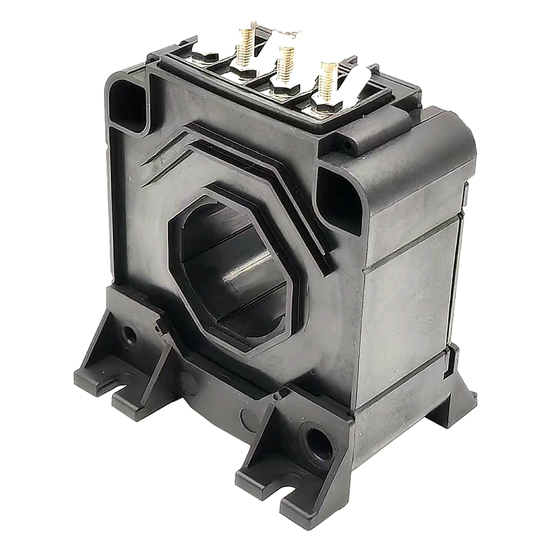
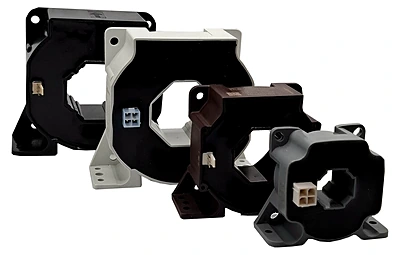
  • OPCO: feeder / converter current feedback
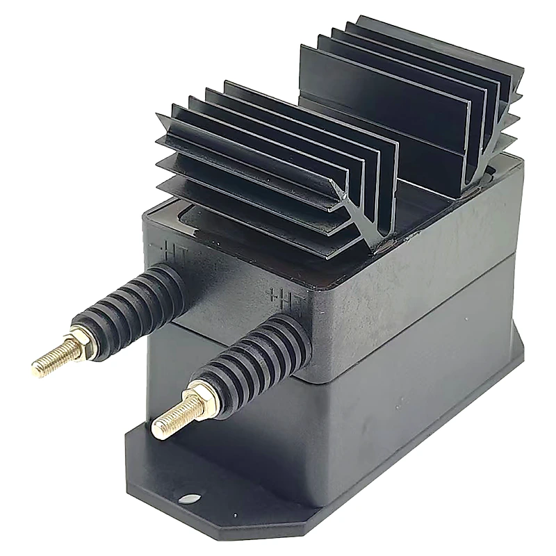
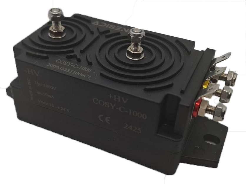
  • COSY-C: DC-bus or converter voltage supervision
  • Key constraints: overload, insulation coordination, EMC, thermal environment and cabinet integration
02 · ONBOARD TRACTION

Traction converter, propulsion & auxiliaries

The onboard chain combines high current, high voltage, switching transients, vibration and railway-specific qualification requirements.

  • TCS: traction-converter, auxiliary-converter and propulsion current
  • HEVS: high-voltage feedback in demanding railway sections
  • GVS: auxiliary / converter voltage feedback where applicable
APPLICATION → SENSORS

Measurement-point mapping for railway engineers

Application zoneMeasurement pointSensor familyEngineering purpose
Traction substationFeeder / converter currentOPCOClosed-loop current feedback for control, protection and diagnostics
Traction substationDC bus / converter voltageCOSY-CIsolated voltage supervision inside trackside power equipment
Onboard tractionTraction-converter currentTCSRailway-focused current measurement for traction power conversion
Onboard propulsionMotor / propulsion currentTCSCurrent feedback for traction motor control and protection
Onboard high-voltage sectionHigh-voltage feedbackHEVSHigh-voltage measurement under demanding insulation constraints
Auxiliary converterAuxiliary / converter voltageGVSVoltage feedback for auxiliary electrical subsystems
RAILWAY STANDARDS & DESIGN CONSTRAINTS

Compliance is part of the engineering decision

EN 50155:2021Electronic equipment used on rolling stock — applicability confirmed per reference.
EN 61373Shock and vibration requirements for railway applications.
EN 45545-2Fire behaviour requirements, including R22 HL2 where validated.
IEC 61010-1Electrical-safety framework referenced by applicable product documentation.
Insulation coordinationNominal voltage, transients, pollution degree, creepage and clearance must be reviewed together.
EMC / PWM environmentSensor behaviour must be verified in the actual converter environment, not only under static conditions.
RAILWAY APPLICATION ENGINEERING

Define the measurement point before choosing the sensor.

Share nominal current or voltage, overload, output, insulation, mounting, connector and railway qualification requirements.

Technical Request →