
MCT-C Series
Compact DC & AC earth-leakage and differential-current sensing.
The MCT-C family is a miniature closed-loop compensated current transducer based on a flux-gate principle. It measures DC, AC and mixed currents with galvanic isolation between the primary power circuit and the secondary electronics, making it particularly suitable for leakage-current, fault-current and differential-current detection in compact industrial and photovoltaic systems.
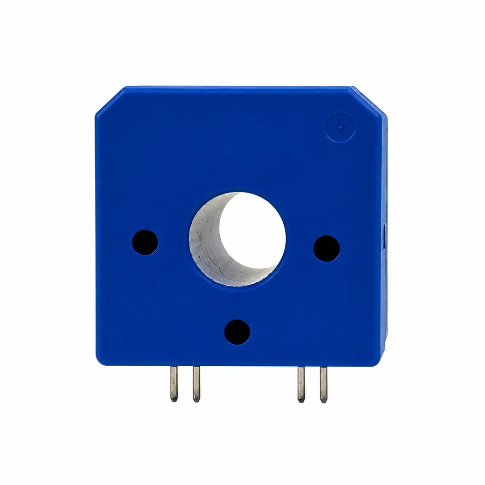
Closed-loop flux-gate architecture for DC, AC and mixed currents
Unlike a conventional open-loop Hall sensor, the MCT-C uses a compensated flux-gate measurement principle. This architecture is particularly valuable when the application requires detection of DC components, AC leakage and mixed-current fault conditions with galvanic isolation.
MCT-C technical characteristics and datasheets
Three validated current ratings are available. Each reference links directly to its technical datasheet.
| Reference | Product code | Nominal current | Measuring range | Supply | Output @ ±IPN | Accuracy | Linearity | Response | Bandwidth | Isolation | Operating temp. | Datasheet |
|---|---|---|---|---|---|---|---|---|---|---|---|---|
| MCT-C-100P4 PDF ↗ | 11200100031200001 | 100 A | ±200 A | ±15 V | ±5 V | <±1% IPN | <±0.5% IPN | <60 ms | DC 40…7000 Hz | 2.5 kV | −20 to +85°C | Open PDF ↗ |
| MCT-C-200P4 PDF ↗ | 11200200031200001 | 200 A | ±400 A | ±15 V | ±5 V | <±1% IPN | <±0.5% IPN | <60 ms | DC 40…11000 Hz | 2.5 kV | −20 to +85°C | Open PDF ↗ |
| MCT-C-400P4 PDF ↗ | 11200400031200001 | 400 A | ±800 A | ±15 V | ±5 V | <±1% IPN | <±0.5% IPN | <60 ms | DC 40…18000 Hz | 2.5 kV | −20 to +85°C | Open PDF ↗ |
Protection-oriented current measurement
MCT-C is positioned primarily as a leakage, fault and differential-current sensor rather than a general-purpose phase-current transducer.
Compact PCB-mount architecture
Simple ±15 V analog interface
The transducer injects a 500 Hz square wave into the primary circuit. In low-impedance primary circuits this may induce an AC current. The controlled datasheets specify the resulting output contribution for each current rating when primary impedance is at least 10 Ω.
Industrial electrical-safety integration
Designing an earth-leakage or differential-current function?
Share the monitored conductors, expected DC and AC residual-current content, primary impedance and protection objective with our technical team.
Request Technical Support →Need another current range or integration format?
ADISENS can review project-specific leakage-current and differential-current sensing requirements.
Request a Custom MCT-C →