
EM / EMT / EMK Series
Compact current sensing engineered directly into the power PCB.
The EM, EMT and EMK families combine a high-sensitivity programmable Hall IC with through-hole primary conductor terminals, galvanic isolation and factory digital calibration. The result is a compact sensing platform for accurate DC, AC and pulsed-current feedback in modern power electronics.
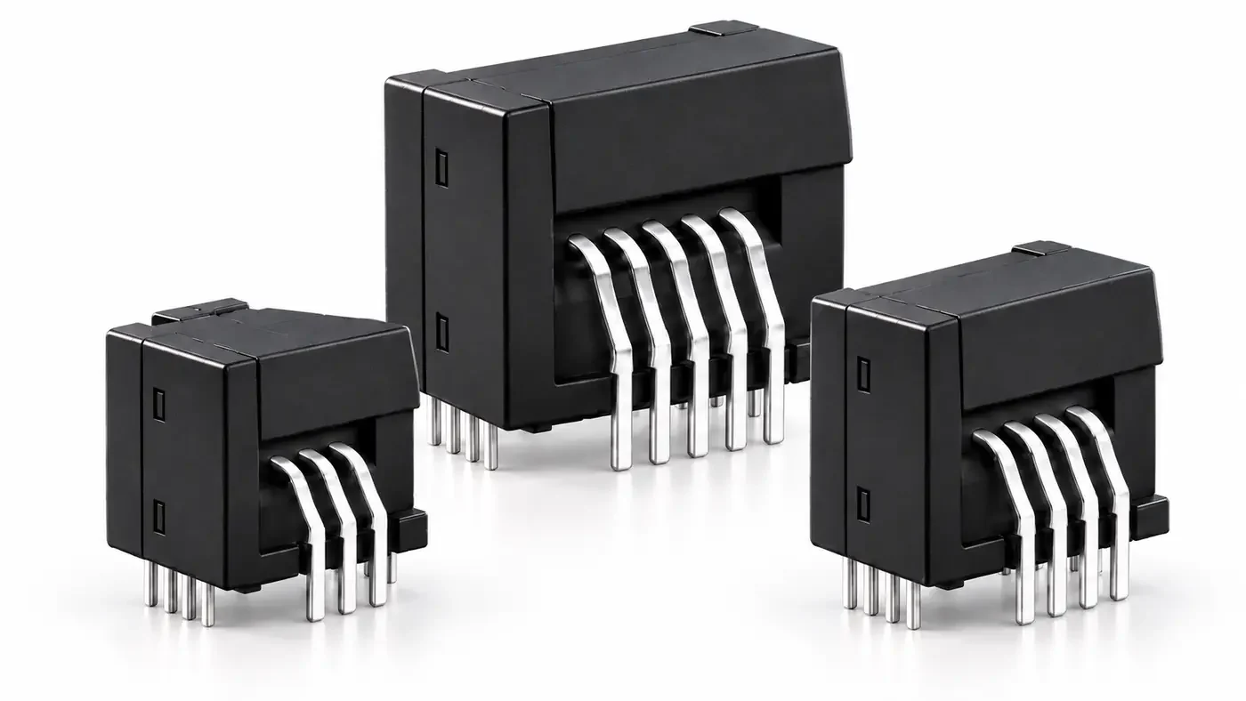
Galvanically isolated Hall-effect measurement inside a compact PCB package
Primary current flows through dedicated through-hole conductor terminals integrated into the sensor package. The magnetic field generated by that current is measured by the Hall element and converted into a calibrated analog voltage. The secondary electronics remain galvanically isolated from the power path, while the analog output is centred around a 2.5 V offset for bi-directional current measurement.
Designed around the switching power-conversion environment
The series is particularly suited to compact converter architectures where current feedback must be accurate, isolated, fast and physically close to the power stage.




Choose the primary-conductor pinout that best matches your PCB architecture
EM, EMT and EMK share the same sensing philosophy and core electrical performance. The principal distinction is the primary through-hole conductor arrangement and associated PCB geometry.
Select a product family below to access reference-level specifications and datasheets.
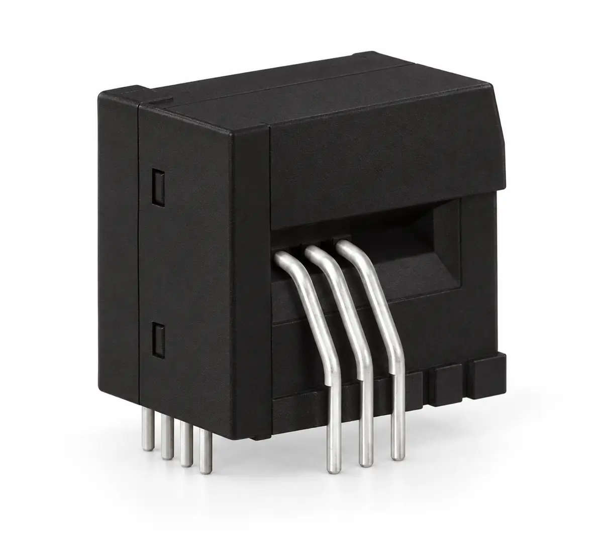
EM Series
15 A, 25 A and 50 A nominal ratings. Compact 3-pin primary topology with 7.62 mm primary pin pitch.
Explore EM Series →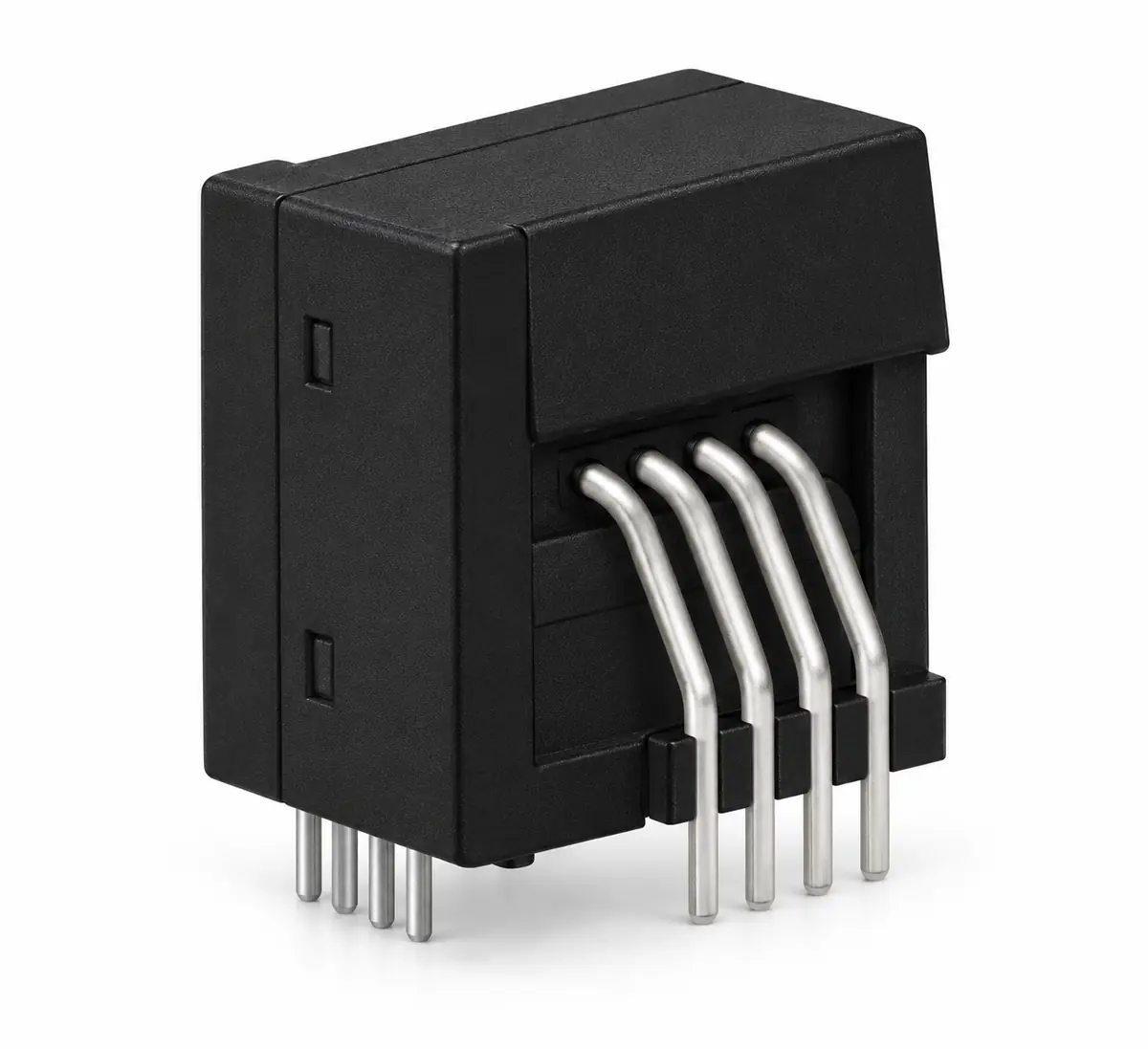
EMT Series
15 A, 25 A and 50 A nominal ratings. 4-pin primary topology with 10.16 mm primary pin pitch.
Explore EMT Series →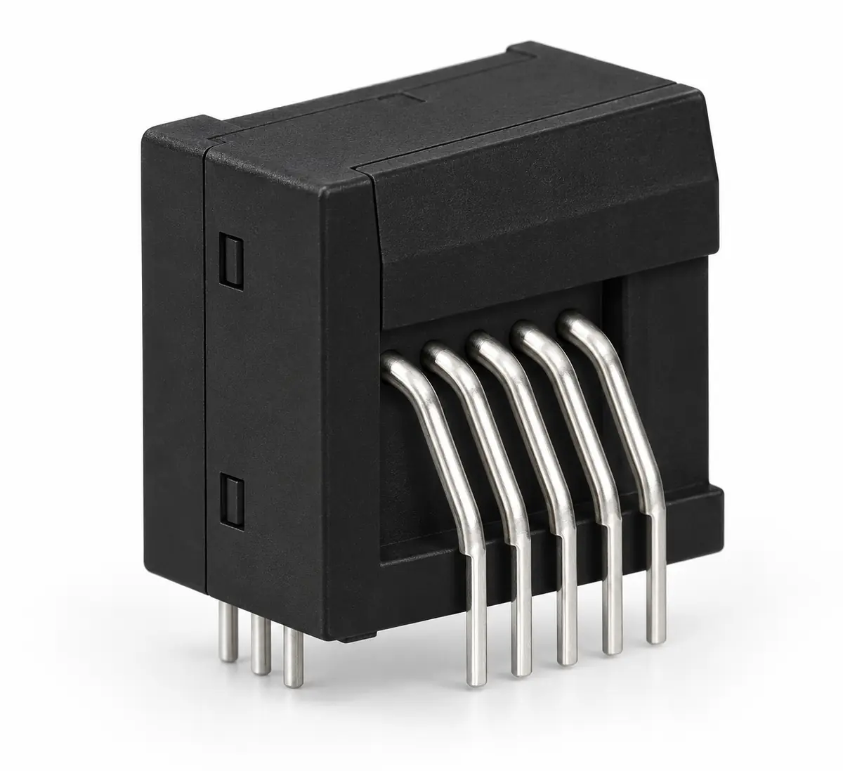
EMK Series
15 A, 25 A, 50 A and 75 A nominal ratings. 5-pin primary topology with 10.2 mm primary pin pitch.
Explore EMK Series →One sensing platform, three PCB integration choices
| Family | Nominal ratings | Primary pinout | Primary pin pitch | PCB electrical clearance | Supply | Typical response | Bandwidth | Dielectric strength |
|---|---|---|---|---|---|---|---|---|
| EM | 15 / 25 / 50 A | 3-pin primary | 7.62 mm | 6.3 mm | 5 V ±5% | <2 µs | 250 kHz | 4 kV AC |
| EMT | 15 / 25 / 50 A | 4-pin primary | 10.16 mm | 6.1 mm | 5 V ±5% | <2 µs | 250 kHz | 4 kV AC |
| EMK | 15 / 25 / 50 / 75 A | 5-pin primary | 10.2 mm | 8.5 mm | 5 V ±5% | <2 µs | 250 kHz | 4 kV AC |
High dynamic capability in a 13 g board-mount package
Typical linearity error at 25°C.
Accuracy at 25°C.
Impulse withstand isolation voltage, 1.2/50 µs.
Clearance and creepage distance along the package.
Operating temperature range.
Housing material classification.
Need help choosing between EM, EMT and EMK?
Share your PCB layout, current range, available board area and required primary routing. ADISENS can help select the most appropriate package and primary-turn configuration.
Request Technical Support →Need another current range or mechanical arrangement?
ADISENS can review application-specific sensing, primary routing and integration requirements.
Request a Custom Solution →